Copped this from the Neo-Geo forums.
[spoiler title=”Tutorial” open=”0″ style=”1″]
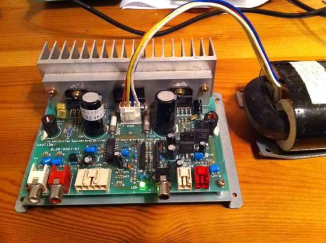
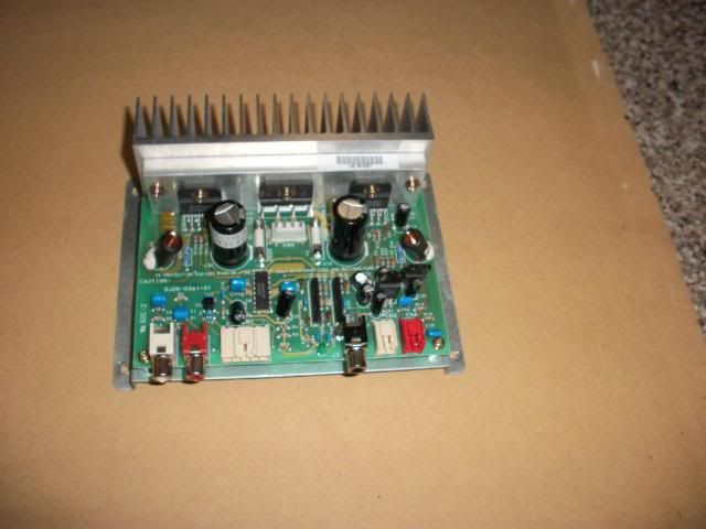
first step, the amp
2, connect the transformer as shown in the pic.
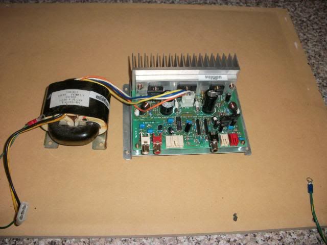
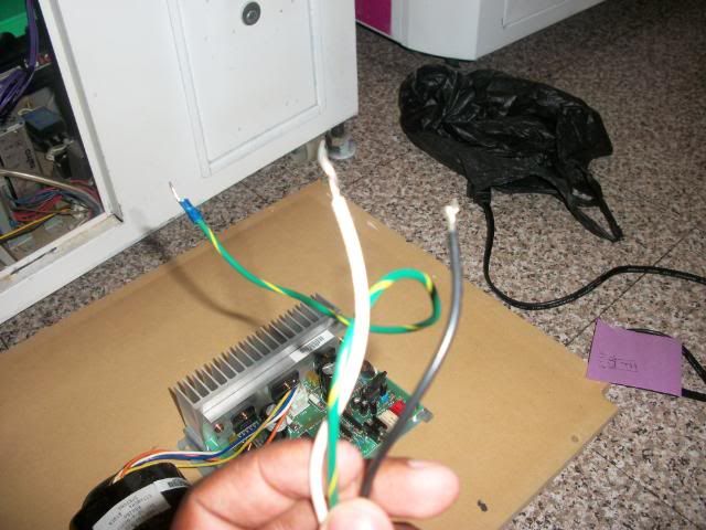
3, connect this white, black, and green cables to the cable that comes out of the transformer.
4, this are the ends of the white, black, and green cables. Those ends need to be connected to your arcade PSU.
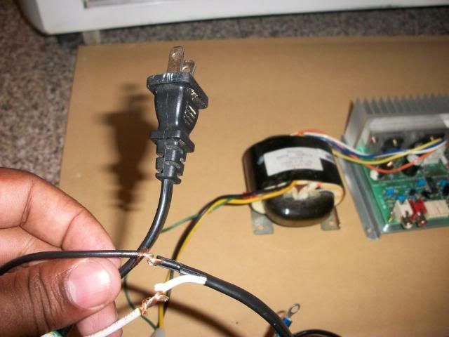
Today I needed to test the AMP, so I had to connect the white and the black cables to a regular AC plug to power the amp.
5, connect the Audio Left (white) and right (red) cables to the amp
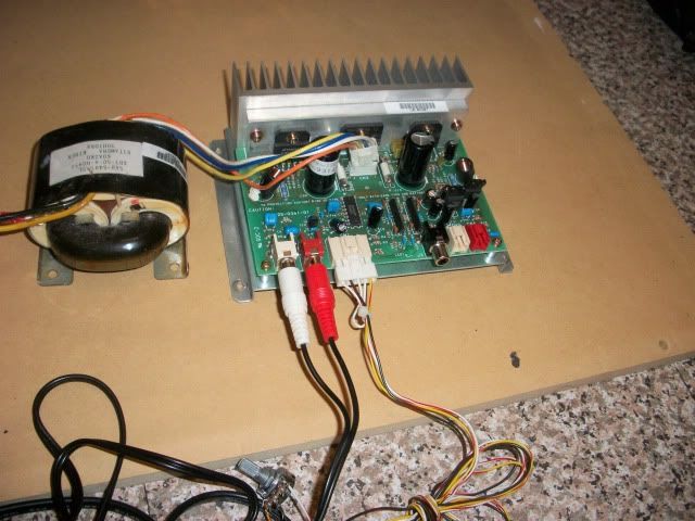
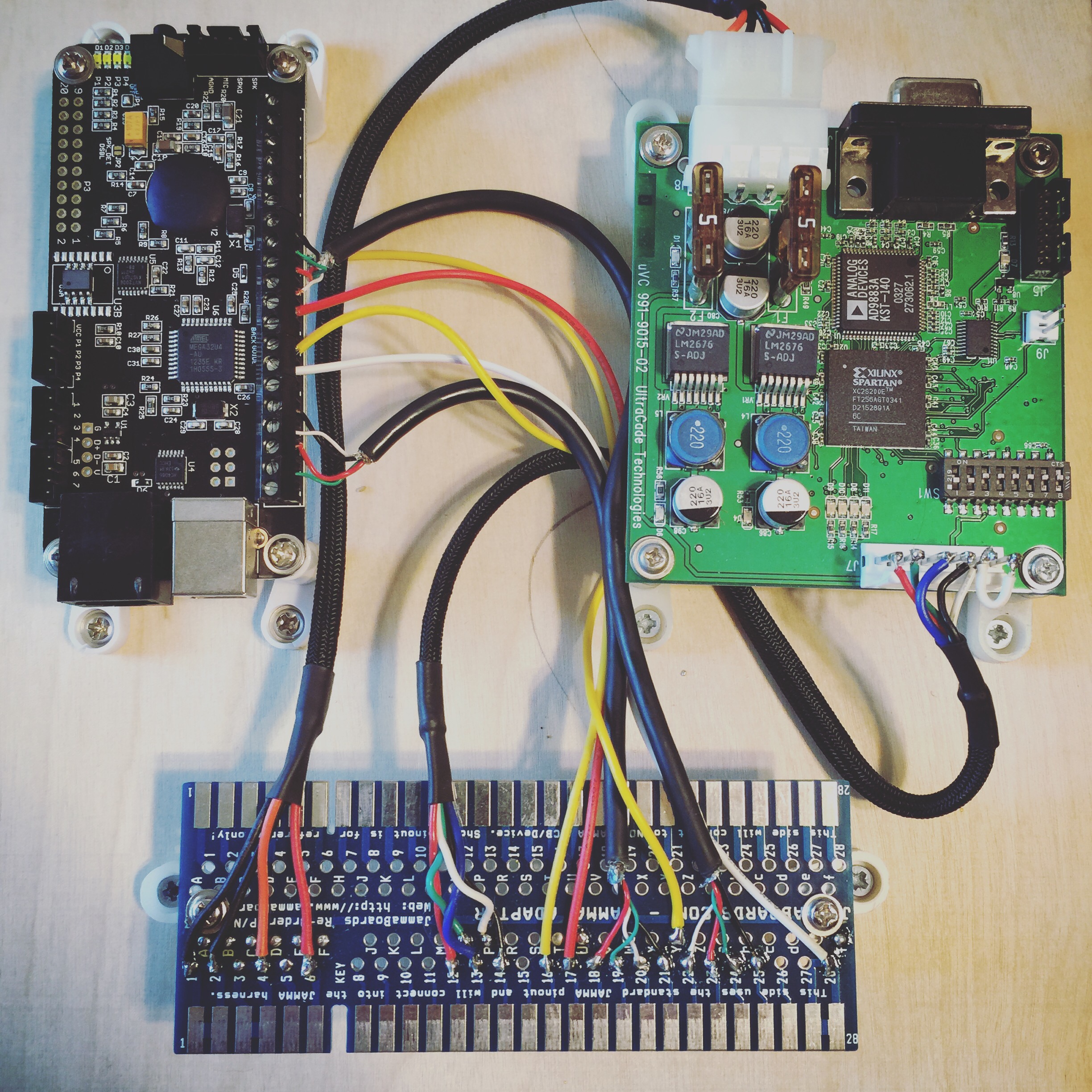
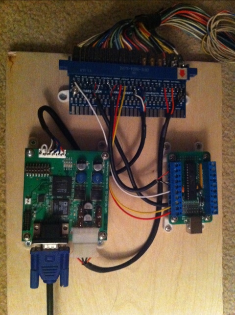
6, and then to the PCB board
7, then connect the volume pot molex to the amp. (left hand side next to the audio plugs). volume pot not pictured, I forgot.
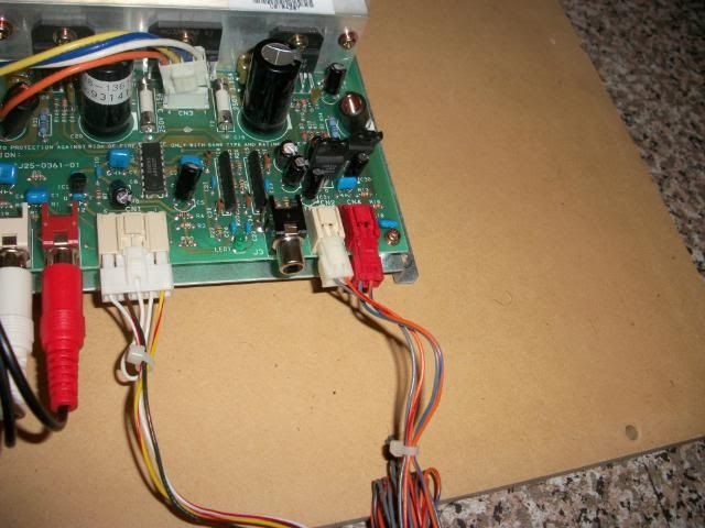
8, connect the audio left and right molex to the amp. (right hand side white and red molex)
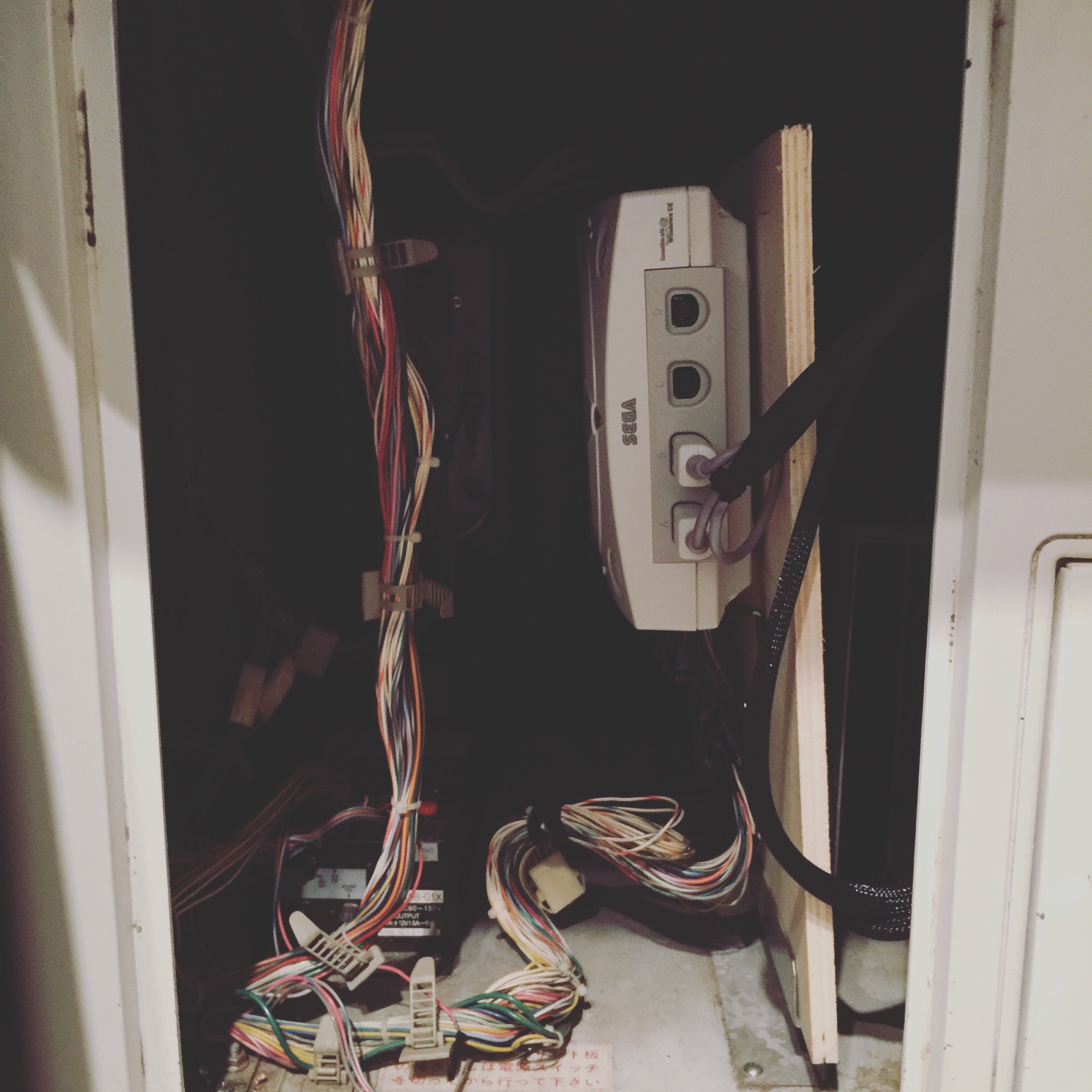
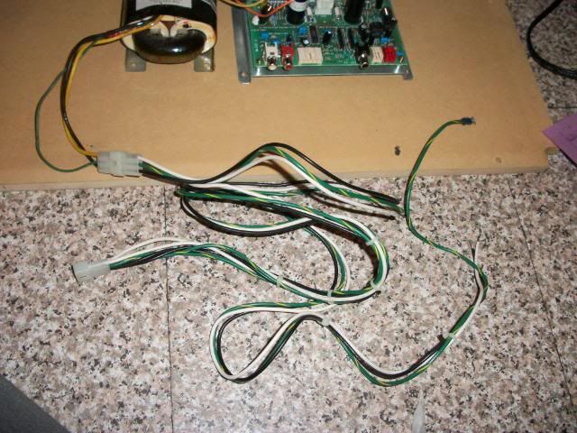
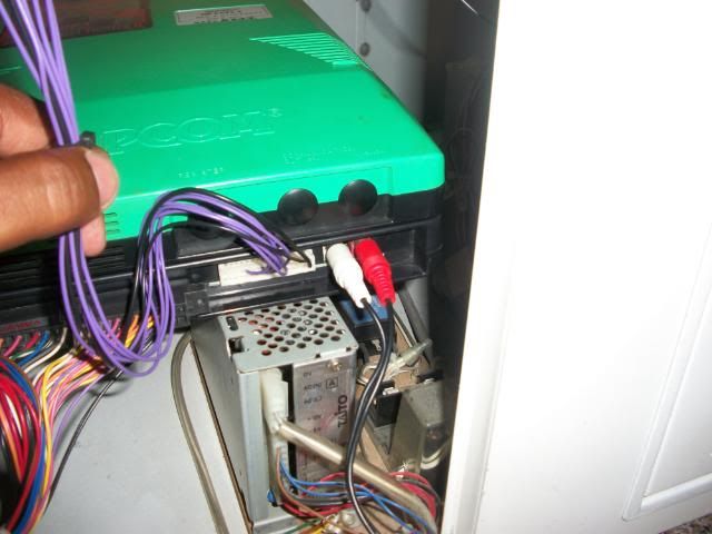
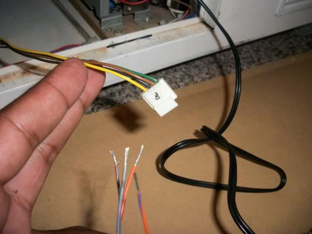
9. there are 4 end cables from the 2 audio molex, 2 from the white molex (left audio) and 2 from the red molex (right audio) they need to be connected to your cab Stereo plug, in my case was the “F” molex in my Egret II. this one
picture of the cables and the molex:
this is a diagram of the Egret II connector (got the pic from some of Kernow post, thanks!)

and the ends of the red and white audio molex are as follow: WHITE (left audio) Grey is L+ and Orange is L-, and RED (right audio) Grey is R+ and Orange is R-
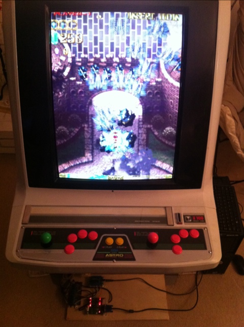
10, next thing you need to do is go to your ARcade pcb setting and set it to stereo, and make sure you put YOUR CAB in stero, (there should be a switch, at least mine has one switch for Mono and Stereo)
I think thats about it. Power on your cab, if the amp is connected to your cab PSU, it should turn on automatically and be ready to work. Hope it helps.
[/spoiler]
I just wanted to archive this incase is ever removed.